Skip to the content

Wind Speed Measuring Devices in Short
Choose a wind speed measuring device that can capture the conditions you need to monitor. Match the device to the input on your logger, display, or controller. Check the operating speed range, start threshold, and accuracy where readings will inform a decision. Then verify the output, power, mounting, and service requirements. A cup anemometer can suit a compatible pulse or frequency input. An ultrasonic wind sensor can provide both speed and direction without a rotating assembly.
A logger that expects pulses and a controller that expects an analog current signal need different configurations. Finding that difference before ordering can save a second installation visit. The same applies to the mounting location. Even with a compatible sensor, wind at the mounting point can differ from nearby conditions.
What Is a Wind Speed Measuring Device?
A wind speed measuring device, also called an anemometer, measures how fast air moves at the sensor’s location. It converts that measurement into a signal or a reading, often in miles per hour or meters per second. A compatible display, data logger, or controller can then use the reading.
A wind speed instrument may supply a raw signal that the receiving device converts to speed. Other instruments calculate the speed internally and send the result to the receiving system. Check which device applies the conversion when you specify the system or replace an instrument.
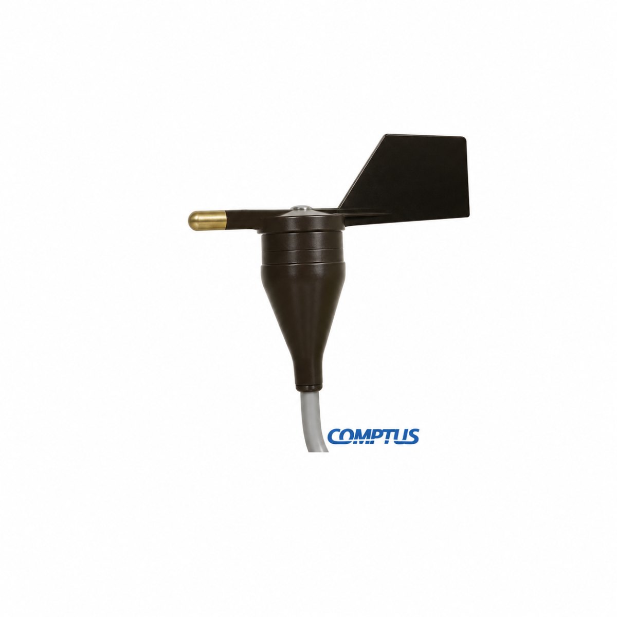
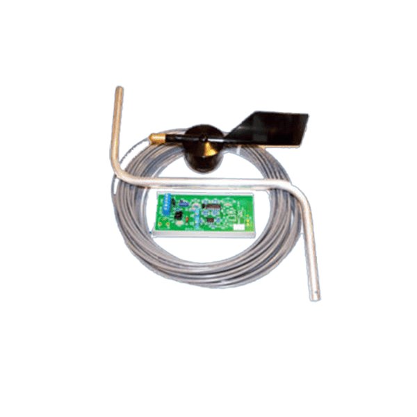
Some projects also need to know where the wind comes from. Pair a cup anemometer with a compatible wind direction vane or use a sensor that measures both variables.
What Types of Wind Speed Instruments Are Available?
Cup Anemometers
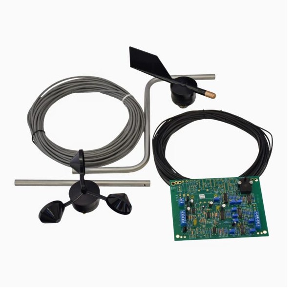
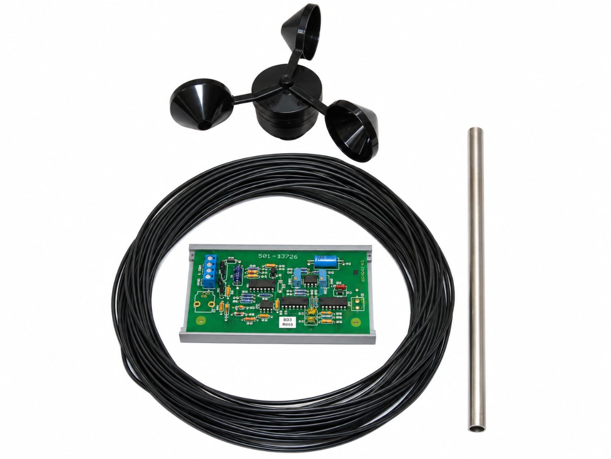
Wind turns a set of cups attached to a shaft. The shaft turns faster as the wind speed rises. Depending on the model, the rotating assembly generates switch closures or an electrical waveform. The receiving device uses the signal frequency and the model’s documented conversion to determine wind speed.
The Comptus A75 series includes cup instruments with reed-switch pulse and sine-wave outputs. The choice depends on the input receiving the signal.
Ultrasonic Wind Sensors
An ultrasonic sensor sends sound pulses between transducers and measures their travel time. Air movement changes the travel times. A sensor with multiple measurement paths can calculate wind speed and direction.
An ultrasonic design avoids wear from rotating cups and their bearings. Check the sensor’s power and communications requirements and plan access for inspection. Comptus offers several output options for its ultrasonic wind speed and direction sensors.
Propeller and Thermal Anemometers
A propeller anemometer measures air movement along the rotor axis. Some designs use a vane to align the propeller with the wind. A thermal anemometer measures how moving air cools a heated element. These approaches can suit different measurement tasks. For example, a thermal probe can measure local air velocity during an airflow inspection. For permanent outdoor use, verify the model’s exposure and mounting limits.
Mechanical vs Ultrasonic Wind Measurement
Start the comparison with the installation and the reading it needs to deliver. A site replacing a cup anemometer may already have a compatible input and a suitable mount. A new station may need speed and direction from one instrument. Each project puts different weight on the questions below.
| What to compare | Mechanical cup anemometer | Ultrasonic wind sensor |
| What the sensor measures | Wind speed. Add a vane when the project needs direction. | A combined model can measure wind speed and direction. |
| How the reading reaches the system | A compatible input or transmitter reads the cup sensor’s pulse or sine wave signal. | A compatible receiver reads the configured analog output or digital communications. |
| What can affect light wind readings? | Check the speed needed to start cup rotation and the published accuracy range. | Check the minimum reported speed and accuracy range for the selected model. |
| What staff need to inspect | Check the cups, shaft movement, mount, cable, and connections. | Check the sensing paths, mount, power, and connections. |
| What to check for cold exposure | Check the operating limits and whether ice can interfere with rotation. | Check the operating limits and whether the model offers heating for the application. |
Include the cost of any input module, transmitter, mounting changes, and recurring access. A sensor swap can grow into a control change if the new output differs from the existing one. Ask the installer to identify those changes while you compare models.
How Accurate Does Wind Measurement Need to Be?
Set the accuracy requirement where the wind data will affect an action or interpretation. A site that records general trends may have different needs from a project that evaluates light winds. A controller responding near a defined operating point needs readings that support that decision.
Ask the person who uses the data which readings would change their interpretation. Use that answer to identify the relevant wind speeds and the amount of measurement error the application can tolerate.
Read the Specifications Together
Check these terms on the current data sheet for the exact model and configuration.
| Specification | What it tells you | What to verify |
| Measurement range | The wind speeds the instrument can report | Whether the range covers the speeds your application needs |
| Starting threshold | For a cup model, the wind speed that starts a stationary rotor | Whether the sensor starts moving under the light wind conditions you need to detect |
| Accuracy | The stated limit on measurement error under specified conditions | The speed range and conditions to which the limit applies |
| Resolution | The smallest increment the instrument reports | Whether the increment is small enough to show the changes you need to see |
| Gust survival speed | The wind speed the manufacturer rates the instrument to withstand | The separate measurement limits that apply during operation |
Check how the manufacturer expresses accuracy. A fixed error limit stays the same across the range where it applies. A limit based on a percentage of the reading grows as the reading increases. Compare instruments at the speeds the application uses. If a project needs measurements close to the starting threshold, confirm the accuracy the data sheet actually specifies there.
Specify Averages and Gust Readings
A wind speed value can represent a recent sample, an average, or a peak calculated over a defined period. Confirm which value the site needs to display, store, or use for control. Specify the sensor response and the controller or logger settings together.
A report can smooth over brief changes if it stores only longer averages. If the project needs gust information, verify how the system detects, calculates, and stores gust readings. Record the relevant time windows so later reviewers can compare records on the same basis.
How Environmental Conditions Affect Wind Sensor Selection
Review conditions at the proposed sensor and at any separate transmitter or enclosure. A sensor exposed above a roof and electronics housed inside a panel face different conditions. Check the operating limits for each part of the installation.
Temperature, Moisture and Debris
Compare the published operating temperature range with the conditions the instrument will face. Check enclosure and connector protection where water or dust can reach them. Inspect the planned cable route for areas where exposure or movement could affect the signal.
Dust or debris can collect around moving parts or on sensing surfaces. Consider how often staff can access the device for inspection. A location that requires special access can change which design fits the site’s maintenance plan.
Freezing Conditions and Strong Wind
Ice can interfere with cup rotation or obstruct an ultrasonic sensing path. Some Comptus ultrasonic configurations list optional heating. Confirm the heating option, electrical demand, and operating limits for the exact model.
Review the sensor’s measurement range alongside its gust survival rating. Confirm the mount and support suit the planned location as well. Define the measurement range the site needs during strong winds. Check how the system flags an unavailable reading.
How Wind Sensors Connect With Monitoring and Control Systems
Identify the device that first receives the wind signal. It might be a data logger, a programmable logic controller, or a building automation panel. A supervisory control and data acquisition system may receive the data from that device. Confirm the input type, available power, and signal conversion before selecting a sensor.
Pulse and Sine Wave Signals
A reed switch anemometer opens and closes a contact as the rotor turns. A compatible input counts the pulses or measures their frequency. Check the input specifications and use the conversion for the selected sensor. Confirm how the system handles light winds and periods when no pulses arrive.
A sine wave model generates an alternating signal. Its frequency varies with rotation speed. Check whether the receiver can read that waveform at the signal levels the sensor supplies. Verify the conversion used to display or store the wind speed.
Analog Outputs and Transmitters
Some controllers accept an analog current or voltage input. A compatible transmitter can convert the sensor signal to the input the controller expects. The Comptus wind speed sensor with a translator uses a cup anemometer. Its analog output options include 4-20 mA. Confirm the selected option and its scaling.
Record what the analog signal endpoints represent. A mismatch in speed ranges or units can produce plausible readings on the wrong scale. Check the displayed and logged readings during commissioning.
Digital Communications and Data Status
With a digital model, confirm the electrical interface, the protocol, and the way the instrument sends each measurement. Verify that the receiving device can read the configured speed and direction values in the required units.
Decide how the system will identify stale or missing data. A calm period can produce a valid zero. Power loss or communication loss can leave the system without a current reading. Agree with the controls team on how the display, trend, or control logic will handle each condition.
What Should Buyers Evaluate Before Choosing a Wind Anemometer?
Create a short specification before requesting quotes. Give each supplier the same information so the proposals cover the same application and signal requirements.
- The intended use. State whether the instrument will support trend logging, a display, or an existing control sequence. Identify the people or systems that will use the data.
- The readings you need. List wind speed, direction where required, units, and the range that matters. Include requirements for light wind detection, averages or gusts where relevant.
- The receiving equipment. Share the logger or controller model, available inputs, and power. Include details for any transmitter or display the site plans to reuse.
- The installation. Describe the mounting location, nearby obstructions, and expected exposure. Include planned cable routing and access for inspection.
- The equipment included. Ask which items the configuration requires, such as a transmitter, mount, or cable. Check which components come with the quoted instrument.
- The verification and service needs. Ask how the team can check the reading at startup. Confirm what documentation, calibration options, and service instructions apply to the selected model.
For a replacement, photograph the existing nameplate and record how the current system interprets the signal. Two instruments can fit the same mount and require different input settings. Bring the wiring and scaling information into the quote review to catch that difference.
Wind Speed Instruments for Different Applications
The application determines what the site should measure and where the reading will be useful.
- Building automation. Identify which building system uses the outdoor wind input. Match the signal to the controller and choose a location that represents the exposure the control sequence addresses.
- Renewable energy. Check the measurement heights, wind speed range, and data intervals in the project plan. Review the calibration documentation the project requires before ordering.
- Agriculture. A station installed on site can record wind conditions relevant to field operations. Position the sensor to represent the area staff need to assess. Agree on the averaging period and how workers will view the readings.
- Industrial facilities and construction. Wind records can support reviews of conditions around outdoor equipment or work areas. Use the site’s operating requirements to determine where the sensor belongs and how staff will access the readings.
- Environmental monitoring and research. Plan for comparable records over time. Document mounting height, exposure, units, and any changes to the sensor or logger settings.
How Installation Affects Wind Measurement
An anemometer reads the air moving where it sits. Buildings, trees, and equipment can shelter it from the prevailing wind or create turbulence. The reading describes the wind at that spot. It may differ from the conditions around the equipment or area the team needs to monitor.
Choose the Measurement Location First
Define the area or equipment the measurement should represent. Review nearby obstructions from multiple directions. An open approach from one side can still leave the sensor sheltered when the wind shifts.
Confirm the mounting height and orientation using the sensor instructions and any project measurement requirements. When the instrument measures direction, verify the directional reference the system will use. Choose an accessible mounting point that supports routine checks.
Check the Reading at the Destination
Secure the instrument and route its cable according to the manufacturer’s instructions. Record the installed height, position, and nearby obstructions. For a combined instrument, verify that the system records speed and direction in the intended channels.
Check the reading in the display, controller, or stored record the team will use. Confirm the units, scaling, and timestamp. Keep a record of the settings and test results. Those details can help explain shifts in readings after a move or logger change.
Wind Sensor Maintenance and Calibration
Follow the model’s service guidance and plan inspections around the site’s exposure and use. A visual inspection can identify loose hardware, damage, or buildup that affects the measurement. Use the manufacturer’s instructions to clean or service the sensor.
On a cup instrument, check the cups and look for drag or irregular rotation. For an ultrasonic model, check the sensing paths and look for buildup or physical damage. On both types, inspect accessible cabling, connections, and the mounting assembly.
Review trends between visits. Long runs of zero readings, recurring gaps, or a shift after installation work deserve a closer look. Check site conditions and the signal path alongside the sensor. Keep a dated record of inspections and configuration changes so the team can trace when a change began.
Calibration compares the instrument with a reference under defined conditions. Follow the manufacturer’s service guidance and any project requirements for the calibration method. Ask what documentation is available for the instrument and keep it with the sensor identifier and installation record.
Choosing the Right Wind Measurement Approach
Choose a configuration you can specify, install, and verify on site. If the project replaces an existing wind anemometer, start with the input and conversion already in use. For a new installation, agree on the required measurements and who will use them before selecting the sensing technology.
Give the supplier the wind range, measurement location, and details of the receiving equipment. Include any requirements for direction, data intervals, or calibration records. Those details let you compare configurations on the same basis and resolve compatibility questions before installation.
To discuss a wind speed measuring device for your site, share your application and input requirements with Comptus.
Does a wind speed instrument need a separate display?
It depends on how staff will use the reading. A logger or control panel may already display the value. If operators need a local display, confirm it can accept the selected sensor or transmitter signal.
Can I compare wind readings from sensors at different heights?
You can compare the records if you account for differences in height, exposure, and averaging periods. Document those details before interpreting a difference as a change in site conditions.
Can one device measure both wind speed and direction?
Yes. A combined ultrasonic wind sensor can report both. A cup anemometer can also form part of a setup with a separate wind vane. Check that the receiving system can record both measurements.
What calibration information should I request when ordering?
Ask what calibration records are available for the model and configuration. If the project specifies a method or document, give that requirement to the supplier before ordering. Keep the records with the instrument identifier.